Build Your Own Network
In this session, we will build some IP networks using a network software emulator GNS3 that supports Cisco routers.
Table of Contents
- Step 1. Preparation
- Step 2. Build a Network with Static Routing
- Step 3. Build a Network with OSPF
- For Beginners
- See Also
Step 1. Preparation
In this session, you do not need VirtualBox. We highly recommend using macOS and this guide assumes that you are on macOS.
Install GNS3
Install telnet and GNS3.
The GNS3 official installation guides can be found on https://docs.gns3.com/.
If you are using Homebrew, you can easily install them with:
$ brew install telnet
$ brew cask install gns3
Setup GNS3
Launch GNS3. The Setup Wizard is displayed when GNS3 starts up for the first time. Select Run only legacy IOS on my computer, check Don’t show this again in the wizard, and click Next.

Click Next.

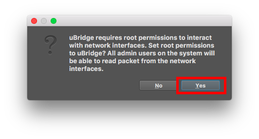
You will be prompted to allow root uBridge. This is required to allow GNS3 to control your network. Click Yes and enter your password.
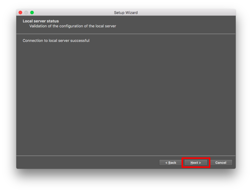
After clicking Next, you should get a validation screen. Click Next.
Once the connection to the local server has been validated, you will see a brief summary. Click Finish.

On this next screen, select Add an IOS router using a real IOS image (supported by Dynamips), and click OK.

The New IOS router template window displays.
Click Browse, select the Cisco IOS image, and click Open.
The Cisco IOS image we assume in this session is c7200-adventerprisek9-mz.152-4.M11.bin.
You will need to provide your own images to use them with GNS3.
GNS3 can decompress IOS images to allow for quicker booting of routers in your GNS3 topologies. This is recommended for a better user experience. Click Yes to decompress the image.
The directory where the decompressed image is stored will be displayed. Click Next to continue the setup.

The Name and platform window displays. Confirm the Platform selection, and configure the router Name. Click Next.

A Default RAM setting is displayed. Make sure that the Default RAM is 512 MiB. Click Next.

Add C7200-IO-GE-E to slot 0. Add PA-GE to slot 1-4. Click Next.

It is important for optimum GNS3 performance that an idle-PC value be selected. If a green idle-PC value is NOT shown then click the Idle-PC finder button to find an idle-PC value. Click Finish.

The Preferences window displays showing the settings you have configured through the setup wizard. Click OK to complete the process.

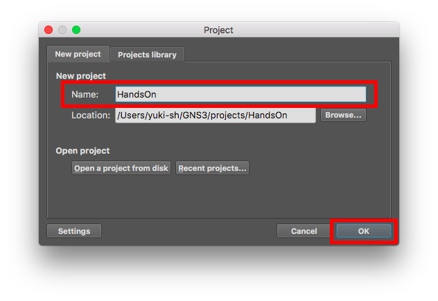
The New Project Window displays. Give your new project a Name and click OK:
The GNS3 workspace displays.
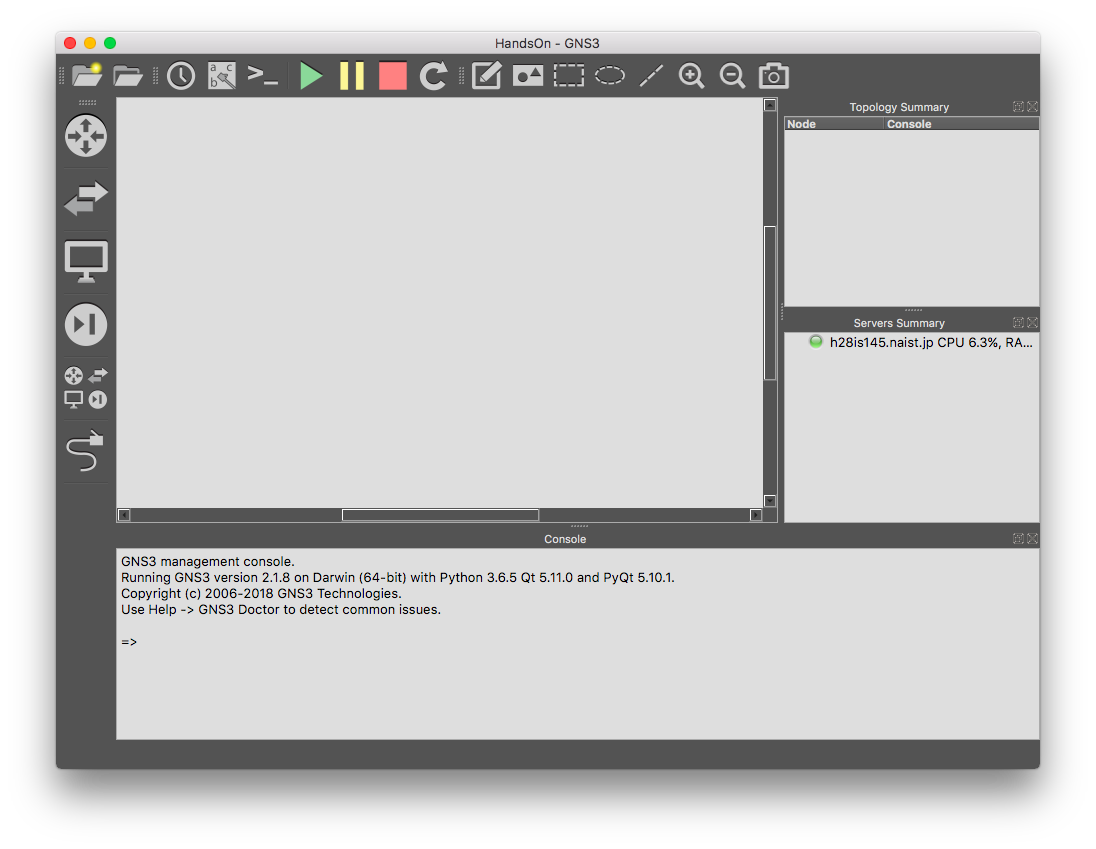
Congratulations! You are now ready to create your own network.
Step 2. Build a Network with Static Routing
Physical Layer

In this step, we make reachable between PC-1 and PC-2 via R1 and R2 with static routing.
Put two VPCS nodes (PC-1, PC-2) and two Cisco 7200 routers (R1, R2). Connect them as shown in the figure above. Then start all nodes and open consoles on VPCS nodes and Cisco 7200 routers.
P2P Links Between Routers
Assign IP addresses on the network 10.0.0.0/30 to R1 and R2.
E.g., for R1:
R1#configure terminal                               # Enter global configuration mode
R1(config)#interface GigabitEthernet 0/0            # Enter interface configuration mode
R1(config-if)#ip address 10.0.0.1 255.255.255.252   # Set the IP address and the netmask
R1(config-if)#no shutdown                           # Make the interface active
R1(config-if)#exit                                  # Exit interface configuration mode
R1(config)#end                                      # End global configuration mode
R1#copy running-config startup-config               # Save configurations
Please configure R2 by yourself.
Then, check reachability between R1 and R2. From R1 to R2 (10.0.0.2) should be:
R1#ping 10.0.0.2
Type escape sequence to abort.
Sending 5, 100-byte ICMP Echos to 10.0.0.2, timeout is 2 seconds:
!!!!!
Success rate is 100 percent (5/5), round-trip min/avg/max = 32/64/156 ms
PC Connection
Assign IP addresses on the network 192.168.0.0/24 to R1 and PC-1.
E.g. for R1:
R1#configure terminal
R1(config)#interface GigabitEthernet 1/0
R1(config-if)#ip address 192.168.0.1 255.255.255.0
R1(config-if)#no shutdown
R1(config-if)#exit
R1(config)#end
R1#copy running-config startup-config
E.g. for PC-1:
PC-1> ip 192.168.0.2/24 192.168.0.1   # Set the IP address and the default gateway address
PC-1> save                            # Save configurations
Please set IP addresses on the network 192.168.1.0/24 to R2 and PC-2 by yourself.
Then Check reachability between R1 and PC-1, R2 and PC-2
From PC-1 to R1 should be:
PC-1> ping 192.168.0.1

84 bytes from 192.168.0.1 icmp_seq=1 ttl=255 time=665.468 ms
84 bytes from 192.168.0.1 icmp_seq=2 ttl=255 time=5.315 ms
84 bytes from 192.168.0.1 icmp_seq=3 ttl=255 time=2.463 ms
84 bytes from 192.168.0.1 icmp_seq=4 ttl=255 time=2.560 ms
84 bytes from 192.168.0.1 icmp_seq=5 ttl=255 time=9.103 ms
From PC-2 to R2 should be:
PC-2> ping 192.168.1.1

84 bytes from 192.168.1.1 icmp_seq=1 ttl=255 time=10.799 ms
84 bytes from 192.168.1.1 icmp_seq=2 ttl=255 time=7.298 ms
84 bytes from 192.168.1.1 icmp_seq=3 ttl=255 time=2.917 ms
84 bytes from 192.168.1.1 icmp_seq=4 ttl=255 time=10.913 ms
84 bytes from 192.168.1.1 icmp_seq=5 ttl=255 time=11.404 ms
Static Route Configuration
Configure static routes to R1 and R2.
When R1 receive packets addressed onto 192.168.1.0/24, R1 should forward them to R2 (10.0.0.2). So, the static route configuration of R1 will be as follows:
R1#configure terminal
R1(config)#ip route 192.168.1.0 255.255.255.0 10.0.0.2  # ip route <destination prefix> <destination prefix mask> <forwarding router's address>
R1(config)#end
R1#copy running-config startup-config
Please configure R2 by yourself.
Check reachability between PC-1 and PC-2. From PC-1 to PC-2 should be:
PC-1> ping 192.168.1.2

84 bytes from 192.168.1.2 icmp_seq=1 ttl=255 time=79.91 ms
84 bytes from 192.168.1.2 icmp_seq=2 ttl=255 time=2.987 ms
84 bytes from 192.168.1.2 icmp_seq=3 ttl=255 time=9.172 ms
84 bytes from 192.168.1.2 icmp_seq=4 ttl=255 time=10.393 ms
84 bytes from 192.168.1.2 icmp_seq=5 ttl=255 time=11.404 ms
Congratulations! Now PC-1 can reach PC-2 on the different network via R1 and R2.
Step 3. Build a Network with OSPF
Physical Layer

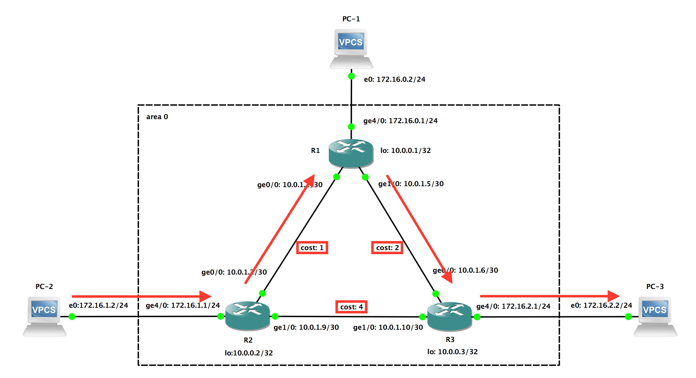
In this step, we make reachable between PC-1 and PC-2 and PC-3 via R1 and R2 and R3 with OSPF.
Put three VPCS nodes (PC-1, PC-2, PC-3), three Cisco 7200 routers (R1, R2, R3). Connect them as shown in the figure above. Then start all nodes.
Loopback Address Configuration
R1 should have a loopback address 10.0.0.1/32.
R1#configure terminal
R1(config)#interface Loopback 0
R1(config-if)#ip address 10.0.0.1 255.255.255.255
R1(config-if)#exit
R1(config)#end
R1#copy running-config startup-config
Please configure R2 and R3 by yourself.
Then, make sure that all routers can reach themselves as 10.0.0.x. E.g. for R1:
R1#ping 10.0.0.1
Type escape sequence to abort.
Sending 5, 100-byte ICMP Echos to 10.0.0.1, timeout is 2 seconds:
!!!!!
Success rate is 100 percent (5/5), round-trip min/avg/max = 32/64/156 ms
P2P Links Between Routers
R1 has two links to R2 and R3.
The P2P link between R1 and R2 is on the network 10.0.1.0/30 and R1 has the IP address 10.0.1.1/30 on ge0/0.
The P2P link between R1 and R3 is on the network 10.0.1.4/30 and R1 has the IP address 10.0.1.5/30 on ge1/0.
R1#configure terminal
R1(config)#interface GigabitEthernet 0/0
R1(config-if)#ip address 10.0.1.1 255.255.255.252
R1(config-if)#no shutdown
R1(config-if)#exit
R1(config)#interface GigabitEthernet 1/0
R1(config-if)#ip address 10.0.1.5 255.255.255.252
R1(config-if)#no shutdown
R1(config-if)#exit
R1#copy running-config startup-config
Please configure R2 and R3 by yourself.
Then, check reachability between:
- R1 and R2
- R2 and R3
- R3 and R1
PC Connection
Assign IP addresses on the network 172.16.0.0/24 to R1 and PC-1.
R1#configure terminal
R1(config)#interface GigabitEthernet 4/0
R1(config-if)#ip address 172.16.0.1 255.255.255.0
R1(config-if)#no shutdown
R1(config-if)#exit
R1(config)#end
R1#copy running-config startup-config
PC-1> ip 172.16.0.2/24 172.16.0.1
PC-1> save
Please configure R2, R3, PC-2, and PC-3 by yourself.
Then, check reachability between:
- R1 and PC-1
- R2 and PC-2
- R3 and PC-3
OSPF Configuration
R1#configure terminal
R1(config)#router ospf 1                                # Enable OSPF as PID 1
R1(config-router)#network 10.0.1.0 0.0.0.3 area 0       # Enable OSPF on a network 10.0.1.0/30 as area 0 (0.0.0.3: wildcard mask)
R1(config-router)#network 10.0.1.4 0.0.0.3 area 0       # Enable OSPF on a network 10.0.1.4/30 as area 0
R1(config-router)#network 172.16.0.0 0.0.0.255 area 0   # Enable OSPF on a network 172.16.0.0/24 as area 0
R1(config-router)#exit
R1(config)#interface GigabitEthernet 0/0
R1(config-if)#ip ospf cost 1                            # Set link cost used in OSPF
R1(config-if)#exit
R1(config)#interface GigabitEthernet 1/0
R1(config-if)#ip ospf cost 2
R1(config-if)#exit
R1(config)#end
R1#copy running-config startup-config
Please configure R2, R3 by yourself.
Check reachability between VPCS nodes.
Congratulations! Now OSPF is working on your network.
OSPF neighbors can be seen with show ip ospf neighbor.
E.g. for R2:
R2#show ip ospf neighbor

Neighbor ID     Pri   State           Dead Time   Address         Interface
10.0.0.3          1   FULL/DR         00:00:39    10.0.1.10       GigabitEthernet1/0
10.0.0.1          1   FULL/BDR        00:00:00    10.0.1.1        GigabitEthernet0/0
IP routes can be seen with show ip route on the router.
E.g. for R2:
R2#show ip route
Codes: L - local, C - connected, S - static, R - RIP, M - mobile, B - BGP
       D - EIGRP, EX - EIGRP external, O - OSPF, IA - OSPF inter area
       N1 - OSPF NSSA external type 1, N2 - OSPF NSSA external type 2
       E1 - OSPF external type 1, E2 - OSPF external type 2
       i - IS-IS, su - IS-IS summary, L1 - IS-IS level-1, L2 - IS-IS level-2
       ia - IS-IS inter area, * - candidate default, U - per-user static route
       o - ODR, P - periodic downloaded static route, H - NHRP, l - LISP
       + - replicated route, % - next hop override

Gateway of last resort is not set

      10.0.0.0/8 is variably subnetted, 6 subnets, 2 masks
C        10.0.0.2/32 is directly connected, Loopback0
C        10.0.1.0/30 is directly connected, GigabitEthernet0/0
L        10.0.1.2/32 is directly connected, GigabitEthernet0/0
O        10.0.1.4/30 [110/3] via 10.0.1.1, 00:00:06, GigabitEthernet0/0
C        10.0.1.8/30 is directly connected, GigabitEthernet1/0
L        10.0.1.9/32 is directly connected, GigabitEthernet1/0
      172.16.0.0/16 is variably subnetted, 4 subnets, 2 masks
O        172.16.0.0/24 [110/2] via 10.0.1.1, 00:00:06, GigabitEthernet0/0
C        172.16.1.0/24 is directly connected, GigabitEthernet4/0
L        172.16.1.1/32 is directly connected, GigabitEthernet4/0
O        172.16.2.0/24 [110/4] via 10.0.1.1, 00:00:06, GigabitEthernet0/0
Try to trace from VPCS nodes.
PC-2 will reach PC-3 via R2, R1, and R3:
PC-2> trace 172.16.2.2
trace to 172.16.2.2, 8 hops max, press Ctrl+C to stop
 1   172.16.1.1   60.631 ms  11.573 ms  10.415 ms
 2   10.0.1.1   35.177 ms  36.198 ms  23.820 ms
 3   10.0.1.6   59.005 ms  55.735 ms  59.348 ms
 4   *172.16.2.2   93.480 ms (ICMP type:3, code:3, Destination port unreachable)
Failure Test
Shutdown R1. OSPF detects that R1 is down and updates paths after a minute. For R2:
R2#show ip ospf neighbor

Neighbor ID     Pri   State           Dead Time   Address         Interface
10.0.0.3          1   FULL/DR         00:00:34    10.0.1.10       GigabitEthernet1/0
R2#show ip route
Codes: L - local, C - connected, S - static, R - RIP, M - mobile, B - BGP
       D - EIGRP, EX - EIGRP external, O - OSPF, IA - OSPF inter area
       N1 - OSPF NSSA external type 1, N2 - OSPF NSSA external type 2
       E1 - OSPF external type 1, E2 - OSPF external type 2
       i - IS-IS, su - IS-IS summary, L1 - IS-IS level-1, L2 - IS-IS level-2
       ia - IS-IS inter area, * - candidate default, U - per-user static route
       o - ODR, P - periodic downloaded static route, H - NHRP, l - LISP
       + - replicated route, % - next hop override

Gateway of last resort is not set

      10.0.0.0/8 is variably subnetted, 6 subnets, 2 masks
C        10.0.0.2/32 is directly connected, Loopback0
C        10.0.1.0/30 is directly connected, GigabitEthernet0/0
L        10.0.1.2/32 is directly connected, GigabitEthernet0/0
O        10.0.1.4/30 [110/6] via 10.0.1.10, 00:00:42, GigabitEthernet1/0
C        10.0.1.8/30 is directly connected, GigabitEthernet1/0
L        10.0.1.9/32 is directly connected, GigabitEthernet1/0
      172.16.0.0/16 is variably subnetted, 3 subnets, 2 masks
C        172.16.1.0/24 is directly connected, GigabitEthernet4/0
L        172.16.1.1/32 is directly connected, GigabitEthernet4/0
O        172.16.2.0/24 [110/5] via 10.0.1.10, 00:00:42, GigabitEthernet1/0
Then, PC-2 will reach PC-3 via R1 and R3.
PC-2> trace 172.16.2.2
trace to 172.16.2.2, 8 hops max, press Ctrl+C to stop
 1   172.16.1.1   9.574 ms  10.557 ms  9.281 ms
 2   10.0.1.10   34.902 ms  22.350 ms  33.447 ms
 3   *172.16.2.2   58.856 ms (ICMP type:3, code:3, Destination port unreachable)

For Beginners
Operation Modes on Cisco IOS
| Operation Mode | Usage | How to Enter | Prompt |
|---|---|---|---|
| User EXEC | With user EXEC mode you can view the settings on the device but not make any changes. | Login or switch from privileged EXEC mode with disable |
R1> |
| Privileged EXEC | In order to make changes to the device, you must navigate to privileged EXEC mode. | Switch from user EXEC mode with enable, from (global) configuration mode with end |
R1# |
| Global configuration | Global configuration mode is where you go to make global changes to the router such as the IP address. | Switch from privileged EXEC mode with configure terminal, from interface configuration mode with exit |
R1(config)# |
| Interface configuration | Interface configuration commands modify the operation of an interface such as an Ethernet. | Switch from global configuration mode with interface <type> <number> |
R1(config-if)# |
Cisco IOS Configuration Basics
Show current configuration:
R1#show running-config
Input candidates:
R1#show ?
  aaa                       Show AAA values
  aal2                      Show commands for AAL2
  access-expression         List access expression
  access-lists              List access lists
  ...
Enter configuration mode:
R1#confugure terminal
Enter interface configuration mode and assign the IP address, then make the interface active:
R1(config)#interface GigabitEthernet 0/0
R1(config-if)#ip address 192.168.0.1 255.255.255.0
R1(config-if)#no shutdown
R1(config-if)#exit
Deassign the IP address and make the interface inactive:
R1(config)#interface GigabitEthernet 0/0
R1(config-if)#no ip address
R1(config-if)#shutdown
R1(config-if)#exit
End configuration mode:
R1(config)#end
Display the differences between the running configuration and the startup configuration:
R1#show archive config differences
Save configurations:
R1#copy running-config startup-config
Reset unsaved configurations:
R1#copy startup-config running-config
GNS3 Basics
Put a Cisco 7200 router:

Put a VPCS node:
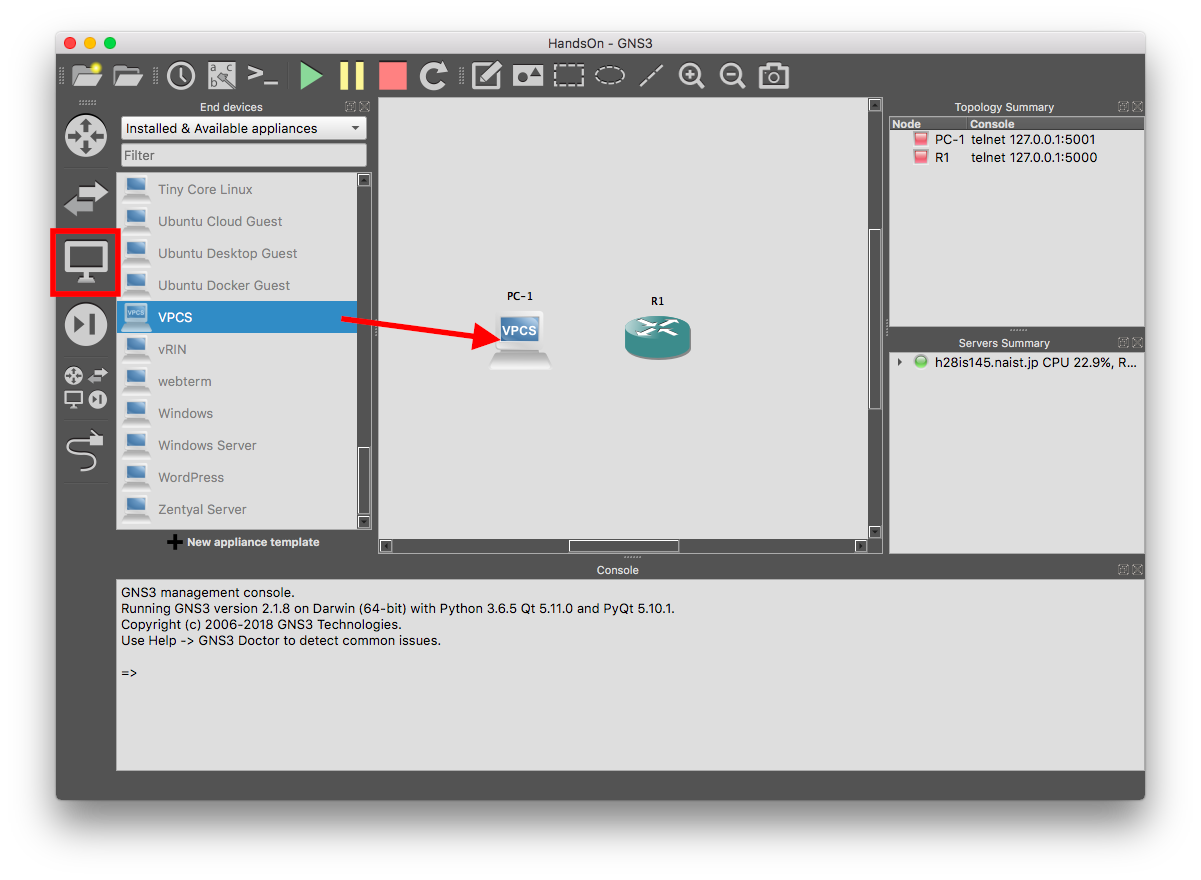
Connect them:

Start all nodes:

Open a console:

(Warm Up) Build a Simple Network
Physical Layer

Make reachable between PC-1 and PC-2, and PC-3.
Put three VPCS nodes (PC-1, PC-2, PC-3), a Cisco 7200 router (R1), and a Ethernet switch (Ethernetswitch-1). Connect them as shown in the figure above. Then start all nodes.
IP Addresses Configuration
Open the console of R1 and assign IP addresses.
R1#configure terminal                             # Enter global configuration mode
R1(config)#interface GigabitEthernet 0/0          # Enter interface configuration mode
R1(config-if)#ip address 10.0.0.1 255.255.255.0   # Set the IP address and the netmask
R1(config-if)#no shutdown                         # Make the interface active
R1(config-if)#exit                                # Exit interface configuration mode
R1(config)#interface GigabitEthernet 1/0
R1(config-if)#ip address 10.0.1.1 255.255.255.0
R1(config-if)#no shutdown
R1(config-if)#exit
R1(config)#end
R1#copy running-config startup-config             # Save configurations
Open the console of PC-1 and assign the IP address.
PC-1> ip 10.0.0.2/24 10.0.0.1   # Set IP address and default gateway address
PC-1> save                      # Save configurations
For PC-2 and PC-3, set the IP address and gateway address in the same way.
Reachability Test Between VPCS nodes
Open the console of PC-1 and ping to PC-3 (10.0.1.2).
PC-1> ping 10.0.1.2

10.0.1.2 icmp_seq=1 timeout
84 bytes from 10.0.1.2 icmp_seq=2 ttl=63 time=23.273 ms
84 bytes from 10.0.1.2 icmp_seq=3 ttl=63 time=22.010 ms
84 bytes from 10.0.1.2 icmp_seq=4 ttl=63 time=15.011 ms
84 bytes from 10.0.1.2 icmp_seq=5 ttl=63 time=15.329 ms
Open the console of PC-3 and ping to PC-2 (10.0.0.3).
PC-3> ping 10.0.0.3

84 bytes from 10.0.0.3 icmp_seq=1 ttl=63 time=30.238 ms
84 bytes from 10.0.0.3 icmp_seq=2 ttl=63 time=22.502 ms
84 bytes from 10.0.0.3 icmp_seq=3 ttl=63 time=18.401 ms
84 bytes from 10.0.0.3 icmp_seq=4 ttl=63 time=18.783 ms
84 bytes from 10.0.0.3 icmp_seq=5 ttl=63 time=22.480 ms
When pinging for the first time, it may fail sometimes due to take time to execute the ARP mechanism.
(To check the ARP table, type show arp.)
See Also
- “GNS3 documentation,” https://docs.gns3.com/
- “Cisco 7200 Series Routers - Cisco,” https://www.cisco.com/c/en/us/products/routers/7200-series-routers/index.html
- “IOS and Configuration Basics - Cisco,” https://www.cisco.com/c/en/us/td/docs/switches/wan/mgx/mgx_8850/software/mgx_r3/rpm/rpm_r1-1/configuration/guide/appc.html
- T. Pummill, B. Manning, “RFC 1878: Variable Length Subnet Table for IPv4,” IETF, 1995. https://www.ietf.org/rfc/rfc1878.txt
- “コンピューターネットワーク・ネットワーク基盤技術 授業資料,” https://www.fumi.org/kaetsu/
- “AS Rank: A ranking of the largest Autonomous System (AS) in the internet.,” http://as-rank.caida.org/
- “Segment Routing - Cisco,” https://www.cisco.com/c/en/us/solutions/service-provider/cloud-scale-networking-solutions/segment-routing.html
- “About Mandara System | NAIST ITC,” https://itcw3.naist.jp/about/mandara-system.en.html
- “WIDE Backbone,” http://two.wide.ad.jp/
- “Highlights | Interop Tokyo 2018,” https://www.interop.jp/2018/en/shownet/highlight.html